
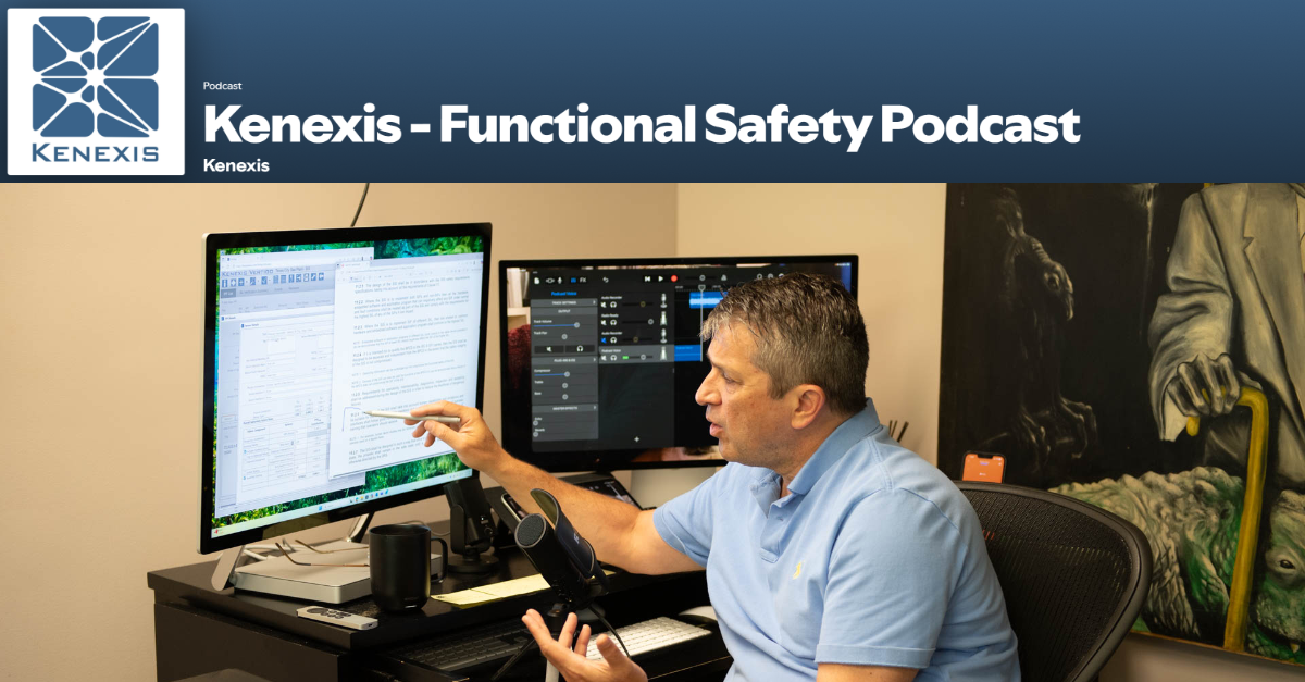
In this episode of the Functional Safety Podcast:
Why does a standard on safety instrumented systems keep demanding “procedures” in its specification clauses? Ed Marszal’s irritation with this recurring tension powers an episode that moves from the practical puzzle of restarting a pump after a low-flow shutdown, through the communication protocols and hardware choices that define SIS interfaces, to the special operating modes that can make or break a coker heater’s spalling cycle. Along the way he sketches how programmers left with only a cause-and-effect diagram will exercise their own discretion on everything from variable names to function block choices, and why bypass authorizations belong in operational software like Vertigo’s alternate protection plan forms rather than buried in instrumentation-group PDFs. For engineers wrestling with the gap between what the standard asks for and what operations actually needs, this is an hour of committee-room candor and field-tested workflow advice.
Confused about what’s really required when starting up or re-starting Safety Instrumented Systems (SIS)? In this episode, we take a deeper look into the often-overlooked details of Clause 10.3.2 bullets 19-23 of the IEC 61511 standard.
Didn’t we already cover this in bullet point 16? Yes—and no. Join us, as we clear up the confusion, revisit the guidance, and break down what you actually need to do to safely and compliantly bring SIS back online.
🔍 What You’ll Learn:
-
The real intent behind Clause 10.3.2
-
Why re-starting SIS isn’t always straightforward
- Practical takeaways for engineers and safety professionals
Tune in to the latest episode of the Kenexis Functional Safety Podcast, hosted by Ed Marszal, President and CEO of Kenexis. Now available on Spotify and Apple Podcasts, Ed offers his expert insights on the IEC 61511 standard.
With decades of experience in safety instrumented systems and as a Principal Engineer, Ed has a unique perspective to offer. He has been an active contributor to the ISA 84 committee since 1994, adding to his deep understanding of the field.
In this inaugural season, Ed delves into the IEC 61511 standard, unpacking the meaning behind each word and providing a thorough interpretation of its application. Through personal stories from his career and committee work, he offers valuable context and insights for professionals in the industry.
Full Episode Transcript
Cold Open
Requirements for starting up and restarting the safety instrumented system. Didn’t we already talk about this? Isn’t this reset?
Introduction and Episode Overview
Welcome to the Kenexis Functional Safety Podcast. I’m your host, Ed Marszal, President and CEO of Kenexis. Kenexis is a technical safety consultancy that helps chemical process industry companies to analyze risk and design engineered safeguards like safety instrumented systems and fire and gas detection systems. Kenexis also provides the industry-leading suite of software tools, including our best-in-class Vertigo software for SIS Safety Lifecycle Management.
In this first season of the podcast, we are going to focus on the IEC 61511 standard, doing a deep dive into the standard, including more depth of information on what the standard means and how to apply it, brought to life with personal war stories and behind-the-scenes discussions of the committee members as we develop the standard in ISA 84 and IEC SC 65.
Before we start, a little disclaimer, I will be providing my opinion on technical and engineering topics. This information is provided on a best effort basis and is of a general nature. The information presented in this podcast might not be applicable to your specific application. It is the obligation of every engineer to thoroughly analyze any system that they are designing and not blindly rely on any general advice presented in this podcast. All right.
Bullet 19: SIS Startup and Restart Procedures
Looks like we’re getting back into it and we are still here in Clause 10.3.2 because there’s just so much to talk about in this action-packed little section of the standard. And we’re continuing on. We finished up with bullet point 18 that talked about failure modes and now we’re on to bullet point 19. We’ll get a couple of these covered over the course of the next hour or so.
And sorry. So let’s just read out bullet point 19. It says that we need to specify the requirements for any specific requirements related to the procedures for starting up and restarting the SIS. Okay. Okay.
So I thought we already talked about this in bullet point 16, requirements for resetting each SIF after a shutdown. Well, okay.
So this is slightly different. It does talk about procedures, which absolutely drives me crazy. I know that I’ve gotten into this. Operating procedures are not specifications. So why are you listing them in specifications? And, you know, I’ve already pointed out the fact that the standards writers, the committee is going to kind of play fast and loose with what a requirement, what a specification actually is and give you a little bit more comprehensive list of all the things that need to happen.
So requirements related to procedures for starting up and restarting the SIS.
Now, procedures are going to be needed to be written by operations. The way this works in most operating companies is that the operations group is going to write a procedure for how they operate the plant. That procedure very well could include interactions that they are going to need to have with the SIS. So the operations group is going to write a procedure. That procedure is going to give some steps related to what actually has to happen in the safety instrumented systems.
But now as instrumentation and control engineers and safety instrumented system designers, we need to think about how the operation staff is going to operate the plant and make sure that we have programmed it so that they can.
And I’ll go back to the archetype of the problem that some people run into being the shutdown that works so well that you can never start the plant back up. And that would be the low flow shutdown on the discharge of a pump. So there are a lot of reasons that you would want to stop a pump if you have low flow, because basically you’re going to destroy the pump at a minimum.
And depending on what’s in the pump, you could have various consequences, even in up to and including causing a major explosion because the material inside the pump gets hot and starts a runaway decomposition reaction that can be explosive.
Now, so we’re going to have a low flow shutdown of the pump, which means when the flow is low, we are going to de-energize the string out to that motor starter and prevent you from pulling the motor starter in and starting the plant back up. Well, wait a minute. I just said you can’t start the plant back up. So how do we overcome this? Well, we need to include some sort of process for being able to restart the plant.
So in this case, what you’re generally going to do is what we at Kenexis refer to as an auto bypass, auto rearm, where you will allow the pump to be started. So the shutdown is not like a true constant shutdown. It’s more of a pulse that shuts the pump down, but then will immediately allow you to restart. So the fact that the flow is low doesn’t prevent you from restarting. And that’s because you’re effectively in a bypass situation a few seconds after the shutdown happens. That’s the auto bypass portion.
And then you will start the pump using a push button. And then there will usually be a timer that says, well, if I don’t get up to my rated amount of flow in a certain time period, then something’s wrong. Just shut the pump back off. But if the flow rate does go up and it exceeds its target set point for a sufficient period of time, then you’re going to basically rearm that safety function. And then when the flow goes low again, it will actually trigger that shutdown of the pump.
So in bullet point 19, it talks about any specific requirements related to procedures for starting up and restarting the SIS.
So ultimately, big picture, we need to design our SIS so that you can restart the plant. This is probably going to involve communications, discussions with the operations group. You might actually want to help them to write the procedures. You’re definitely going to get their input when you’re designing your shutdown system to understand what they expect when they’re going through this restart process.
So that procedures word in this bullet point has always thrown me a little bit because, again, procedures and specifications are diametrically opposed. They are not the same thing. Specifications are supposed to be attributes of pieces of equipment as opposed to procedures or instructions for human beings on how to interact with that equipment. But, you know, I will take this with a grain of salt.
Bullet point 16, talking about resets. And bullet point 19, part and parcel is the same exact thing, in my opinion.
Now, there is a little bit of additional emphasis on the starting up portion. So you might want to have some procedures, not for the operations group, but for the instrumentation and control group, the maintenance group.
If you do what we call a black start, so we’re going to start it up from a completely cold, de-energized state, there may be additional tasks that you need to perform as a maintenance person to get that PLC up and running, to load up its initial software parameters. So, you know, it’s not uncommon that there’s a list of parameters that get read into memory when a safety instrumented system powers up from a cold start. So that’s also part and parcel of this bullet point.
Bullet 20: SIS Interfaces with Other Systems
Okay, moving on, bullet point 20. Bullet point 20 says, All interfaces between the SIS and any other system, including BPCS and operators. Hmm. Hmm. Hmm. An operator is a system that the SIS would want to interface with. Are we talking about brain implants here? Are we moving on to Neuralink, where the SIS is going to be jacked directly into the human skull? So we’re… No, no. We are a long way from that in terms of what the Standards Committee is talking about.
So what do I mean by interfaces? Well, the safety instrumented system most of the time is going to be a computer. And that computer can communicate digitally with other computers. The most common interface is going to be between the SIS and the basic process control system operator interfaces. So the HMI, human machine interface, is the most common one of these. But there are other interface devices. You might be sending signals to the basic process control system for display purposes, historian purposes.
And there are a lot of other systems that might want to get information from the SIS so that connected equipment can respond to what the SIS is doing to make communication of the plant status and interaction with the plant go a little bit more smoothly.
So we need to define all of the interfaces between the SIS and any other system. And we are in specification mode. So we need to think about how we’re going to do it in terms of the hardware.
So whether that is cards in the safety instrumented system that are going to speak via TCP IP or whether you’re going to have a card that speaks Modbus using an RS-232 cable straight from the 1980s. We need to decide how we’re going to do that communication in terms of what is the physical equipment and how do we configure the safety instrumented system to do that communication.
You might need to give some thought as to what data points we’re going to communicate, how they’re going to be communicated. So there’s a decent amount of work involved in bullet point 20.
And that work begins with creating a list of all of the external systems that the SIS is going to communicate with. And then for each of those systems, you need to define what is the hardware that is going to be used for the communication. That’s going to start with a card usually in the safety instrumented system, a decision on what type of protocol, whether it’s going to be TCP IP, UDP, Modbus, Modbus Plus. There’s a long list of protocols that are available. That’s going to include the hardware for the signal transmission. So are you going to use fiber optics?
Are you going to use copper wires? Are you going to use smoke signals? Are you going to use mental telepathy? What is the actual hardware on which the signal is going to travel all the way through to the receiving device?
So the receiving device is usually going to get specified as part of the basic process and control system or whatever the system is that’s receiving the signal. But all this needs to be thought through in terms of the equipment that you need to purchase for each connection. And then also, how am I going to configure it?
So what information am I going to send across? How is it going to be sent across? This could be as complex as creating a list of all the variables that you’re going to communicate and how that communication is going to happen.
I know that back in the early 90s when I was still working at UOP and we were building custom safety instrumented systems for some of the more complex processes at UOP, we had to basically come up with a list. It was the mid-90s, early 90s. We were still using a lot of Modbus to make these communications go across. And you need to think about what are all of the variables you need to communicate. Is it a two-way communication? Is it a one-way communication? What is the variable type that am I sending? Am I sending floating points? Am I sending integers? Am I sending binaries?
A lot of stuff here.
So in the SRS phase, you can kind of keep it lighter and higher level. In the detailed design phase, that’s where you’re going to need to go kind of data point by data point to drive it through. So who am I communicating to? How am I going to do that communication in terms of hardware and also in terms of software? And on the software, I’m specifically talking about the communication protocols.
Bullet 21: Plant and Equipment Modes of Operation
Okay, bullet point number 21. This is something that gets skipped a lot because a lot of engineers in the chemical process industries are kind of, you know, fixated on normal continuous operations. Just a bullet point or two ago, we talked about starting up and restarting.
But for bullet point 21, we’re going to talk about modes of operation. So let’s read through the bullet point as a whole.
Bullet point 21 says that you need to write specifications for a description of the modes of operation of the plant and requirements relating to SIF operation within each mode.
Now, some people might kind of go off the farm on this one and get a little bit too theoretical. Really, we’re not interested in creating a list of modes of operation.
What we’re really interested in is making sure that if a SIF has to do something special in a certain mode of operation, that we’re going to document that when we’re talking about the SIF. So there’s no need to create a list of modes of operation that stands alone by itself. But we need to think about what the modes of operation are and make sure that different safety instrumented functions are equipped to work in those modes of operation.
So for instance, in oil refining, there is a process unit called a cocker where we’re going to take very heavy oil and we’re going to heat it up really, really hot, which results in thermal cracking. That thermal cracking results in lighter, more valuable hydrocarbon products, but it also results in coke, which is going to be eventually a solid powder. Now, these heaters, you start the cracking process in the heater tubes and then it continues as the material travels into the coke drums where that coke is supposed to accumulate.
But eventually, we have built up so much coke in the heater tubes that we need to remove that coke through a process called spalling, which is, it’s, I don’t want to go into the details. We’re basically going to clean out the tubes. Now, when we’re doing the spalling of the heater tubes, we are not flowing oil through those tubes anymore.
So for that mode of operation, we need to consider this because normally if we lose flow of oil through heater tubes, we want to shut the heater off because we’re going to overheat the tubes, melt them, and destroy our heater, basically.
But we’re going to do this spalling activity while the plant is online and running. And even though there’s no oil flowing through the tubes during this process, we don’t want to shut down the heater. We want the rest of the tubes to continue in operation. So we need to have logic to allow us to go into spalling mode.
And when we’re in spalling mode, the safety instrumented system needs to know that, okay, even though I’m seeing a low oil flow through this tube, do not shut the heater off. So some of the other modes of operation might be that during startup, you might want to bypass a low flow shutdown.
So start of run, end of run. So at end of run, you might want to allow a reactor to be hotter than it is at the start of run because at the end of run, the catalyst has been coked up or poisoned to where we, it’s a lot harder to initiate a runaway reaction so we could push it a little bit harder.
So for bullet point 21, what we are not looking for is some sort of document that says, here’s a list of all the modes of operation. Although, having that list of modes of operation might be something that you might want to generate as a work tool to go through all the safety instrumented functions.
So create a list of the modes of operation and then one by one go through all the safety instrumented functions and ask yourself or ask the team, okay, does this safety instrumented function need to behave differently in one of these modes of operation? And honestly, what you’re going to find is that for 99% of the safety instrumented functions, it’s going to behave exactly the same all the time, which honestly is what we want.
Because that kind of goes back to that keep it simple principle. If we have a whole bunch of special modes and special exemptions, it’s you’re creating a situation where you’re more likely to generate human errors while you’re going through your design process.
So kind of summarizing for bullet point 21, create your list of modes of operation of the plant. And you know what? There are specific modes of operation related to equipment too.
So for instance, the one that comes to mind for me all the time is auto calibration. So if I’m auto calibrating a gas detector that might be part of a safety instrumented function, I don’t want to shut the plant down while that calibration is happening. So I need to have an auto calibrate mode. So it’s not just the operation of the plant. It’s also the operation of the piece of equipment. So create that list of all those special modes.
Go through all your safety instrumented functions. And if the safety instrumented function needs to do something special in that mode of operation, document it.
Now, where do you document it? Well, this is logic. So this is going to need to show up in the logic description.
And at Kenexis, when we’re using our best-in-class Vertigo software, the place where you document the logic of the safety instrumented system is in the cause and effect diagram. And if a safety instrumented function needs to operate in a special way during special modes of operation, that’s a place where you’re going to want to make a note in the cause and effect diagram that describes what this extra feature of the logic is.
So you might want to say something like note 1 or N1 in the cause and effect diagram intersection. And that’ll clue the reader that they need to go look at note 1, which might say that there is a spalling operation that is going to require you to put this device in a bypass while that’s going on. And you could describe that in a lot more detail there in the cause and effect diagram notes. Okay.
So that is the description of modes operation and a little bit of workflow help, if you will, for how you would want to consider that and implement that in your workflow when you’re creating your safety requirement specifications.
Bullet 22: Application Program Requirements
All right. Bullet point 22 states, and this is a bit of a, I don’t want to say it’s a cop out. We’re, we’re, we’re, uh, in the programming world here, we, we, we’ve got ourselves a go-to statement in bullet point 22.
So, uh, bullet point 22 states that you need to develop requirements for the application program safety requirements as listed in 10.3.2. Wait a minute. 10.3.2. Isn’t that where we’re at? Um, so not only do we have a go-to, we’re going to where we already are. All right.
Let me kind of, uh, unpack the front part a little bit and ignore the as listed in 10.3.2 a little bit. You need to write specs for application program requirements.
The code that you write in your safety PLC to make the safety instruments, instrumented system do what we want it to do.
Now, I’m not going to belabor that a whole lot right now because we have an entire section on software in Clause 12. So when we get into Clause 12, we’re going to be doing a deep dive, uh, into what you need to specify. But let me kind of hit some of the highlights since we’re, since we’re talking about it, um, right now.
So application program requirements.
What is happening today for application program requirements at the very low end? At the very low end, people are writing software based on a cause and effect diagram, period, full stop. That’s happening. There’s no additional information at all in a lot of cases, uh, for how the application software, uh, should be written. Is that the end of the world? No. A lot of, you know, the software for a safety instrumented system is generally very easy to write, especially if you’re using function block diagrams or ladder logic, some other limited variability language.
Um, so leaving the programmers at their own, uh, decision-making process to how to implement the cause and effect diagram is not the end of the world.
Now, if you unpack that, there’s a very key statement in there. And that’s that if all you do is hand the programmer a cause and effect diagram, they’re at liberty to use their own discretion for every other part of the programming process, which is going to include stuff like variable naming. Uh, it’s going to include, uh, it’s going to include what function blocks they use and how those function blocks are tied together. They might have their own custom function blocks that they’ve developed.
So you’re probably going to want to spend a little bit of time and effort, uh, putting some guardrails around what the programmer is going to be able to do to make sure that the end product that you get is consistent with your expectations. It’s consistent with how the rest of the plant operates. So, um, that’s going to include things like variable naming conventions. That’s going to include preferences for function blocks that are used, uh, in, uh, you know, a variety of different situations.
Uh, it might go into, uh, you know, some, some of the more fine details of program execution in terms of sequencing. Uh, it might limit what languages are allowed to be used. Maybe you wanted function block diagrams, you handed somebody a cause and effect, and they gave you ladder logic. So there is space in those SRS general requirements to help more tightly nail down what your expectations are from a programmer, uh, in terms of what they are going to deliver to you.
Now, a lot of companies are going to take that information and put it into a separate software development spec. So in the SRS, all you need to do is refer to that external document and you’re good to go. Or, hey, you know, if you’re in vertigo, you’re creating your safety requirement specifications. Uh, those general requirements are a good place. You can, might want to have your own section 5.10, 5.11, whatever you want. That lists out kind of bullet point by bullet point all those software requirements that you want to constrain your programmers to.
Especially if those programmers are outside the company, uh, potentially, you know, the equipment vendor or an EPC company.
Bullet 23: Bypass Procedures and Compensating Measures
Okay, let’s continue on. We are now moving on to bullet point 23. We’re making a little bit of progress today, uh, in terms of knocking out some of these bullet points. Uh, the next bullet point is a long one. So I’m just going to go ahead and begin by reading it out again.
So, uh, the safety requirements or you, you shall specify requirements for bypasses, including written procedures to be applied during the bypass state, which describe how the bypasses will be administratively controlled and then subsequently cleared.
Okay, so I’m sure those of you who know me, those of you who’ve been listening to this podcast are bracing yourselves for the tirade I’m about to go on. And what is the word that triggers my tirade? The word is procedures. Procedures. Procedures are not specifications. Specifications are not procedures. Never intermingle specifications and procedures because the person who needs information is not going to get it. Uh, in this specific case, uh, we’re talking about a plant operator needs to understand what they need to do when the SIS is in bypass.
So, if, where does the operator get his information? The operator is not going to go to an SRS document that’s controlled by the instrumentation and control group to get operating procedures. These procedures need to be with the operations group.
So, you know, for every item in the SIS that can be bypassed, if you’re planning on operating the plant with that thing in bypass, you need some sort of description of how that needs to happen.
And that description is going to be discussed in clause 11.3. We’re probably going to spend an entire day talking about clause 11.3, honestly. Uh, but it is something that we at Kenexis will refer to it as an alternate protection plan. Uh, but the standard calls it compensating measures. So, in a lot of cases, compensating measures are human interactions with the process via procedures.
So, what does that look like? Well, if I put a level device into bypass and I want to continue to operate the plant, what might my options be?
So, what I’m going to do, and you can’t see what I’m doing on the screen right now, but I am going into KISS. I’m going into the Kenexis Integrated Safety Suite. I am going to open up our Vertigo application. Um, and inside our Vertigo application, there is a, um, a section related to bypass authorizations. So, looking at Vertigo, there is a tab, uh, with a little key on it that’s labeled bypass authorization, if you look at it in the tooltip.
And when you bring that up, it’s going to allow you to add a new record. Now, for each record, this is where you basically track your bypass authorizations.
Now, there’s a reason that I’m bringing this up, is because I’m talking about where do you need to document this information.
And a piece of paper in a PDF file that sits with the instrumentation and control group is not the right place. Someone is going to need to access a procedure. Okay.
So, if you look at Vertigo and you say that you want to create a new bypass authorization, it’s going to ask you, what are you bypassing? So, you can select the sensor or a final element. And then, if you select the sensor, it’s going to ask you, well, which sensor do you want to bypass? Because in Vertigo, we have a list of all of the sensors and all the final elements. Now, when you select that, it knows the specific device that you’re trying to bypass. Let’s say that that device is LT-101B. The next thing that’s going to happen is it’s going to ask you for the type of bypass.
So, there are different requirements. And we’ll get to this in Clause 11.3. But there are different requirements for what you need to do with a bypass depending on a couple things. And number one would be what is the reason that you’re performing the bypass? Is it just simple repair or maintenance? Or is it something more complex? Like I’m about to go into the trip state and I don’t want to. So, I’m going to put it in to bypass, which is, generally speaking, a horrible thing to do.
And then, also, we have some assumptions about how quickly we’re going to be able to repair a device. So, if you’re going to exceed the amount of time that you assumed in your SIL verification calculations, the amount of risk that you’re at is going to be a little bit higher.
Finally, there’s redundancy. So, if I have a two out of three vote and I’m bypassing one leg of the two out of three vote, the other transmitters are generally going to be able to do the job for that 72, 48 hours, whatever the duration is of your repair. So, the compensating measures, if you have redundancy, is effectively, well, the other instruments that are still there and in an operation. Whereas, if you don’t have any redundancy, you’ve got a one out of one vote, well, now it’s a little bit trickier because you need to rely on something else.
So, I’m going to pick in vertigo what we call a type 3 bypass. So, for a type 3 bypass, it’s a one out of one vote. I’m not part of a fault tolerance system. But, I am going to perform my repair within the meantime to repair. So, here, you need to define your alternate protection plan or your compensating measures.
And as soon as you do that, inside our vertigo software, you’re going to see that it pops up a form for you to fill out that is the alternate protection plan. And this is where that information should reside. So, in terms of, you know, that bullet point, so, achieving bullet point number 23 in clause 0.10.3.2, I would tell you that the optimal place for that information is going to be in the alternate protection plan fields for each sensor and each final element inside of vertigo. So, that alternate protection plan, what does it include?
Well, there are a few items that you need to fill out. So, these are the questions that you need to answer.
Number one, what process variable or variables must be monitored? So, if I’m taking a level transmitter out of service, maybe I need to monitor that level with the BPCS measurement, or maybe I need to go out to the field and look at a sight glass. The second question is, what are the manual trigger points for the monitored variables? So, maybe the SIS trips at 90%, but if a human being is replacing this device, maybe I want to trip at 70% instead. The third question is, who is responsible for performing the process variable monitoring?
So, I want to know who the person is who’s going to be doing this activity. So, you might have a dedicated outside operator that’s been brought in on overtime just to perform this task. Next question, who is responsible for performing the manual shutdown action? Now, maybe that outside operator is going to go to a manual valve and turn the wheel, or maybe they’re going to call into the control room and have the board operator press a button to maybe take a BPCS control loop, put it into manual and close a valve, for instance. So, who is going to be doing that trigger action?
Next question is, what specific actions must be taken to perform that manual shutdown? So, what is actually going to physically happen to get yourself to the shutdown state? Next question, is a yes or no? Something to think about? Definitely a case for some honesty. Can a manual shutdown be performed within the process safety time? If the answer is no, you shouldn’t be attempting this, and you should just allow the plant to shut down, especially if it’s a sensor.
But if it’s a final element, you know, maybe you had a valve that failed a partial stroke test, and you can’t perform the alternate protection plan in the process safety time, but, you know, it’s your only option. So, some discussion, some thinking.
Next question, is there sufficient independence between normal operating staff and the alternate protection plan? So, we want to get you to really think that, you know, hey, having the board operator keep an extra eye on this variable, yeah, that’s not going to wash. That’s, that’s kind of pushing it a little bit. So, think about whether or not what you’re asking the operator to do, they can reasonably do, and they’re not going to be distracted from their normal job.
And if their normal job is that easy, all right, anyway, next question, last question, a bypass risk assessment has been performed and is acceptable, if required. Now, why do you require a bypass risk assessment? And that would be if you’re doing something funky, like you’re running the bypass for longer than the mean time to repair that you documented, elevating the risk, or you’re performing a bypass for a reason other than just routine maintenance and repair. So, a lot of times this is not required.
Now, once you’ve filled out all these variables in, in effigy, when you hit the insert button for this specific case, the software is going to save all that information. So, the next time you want to bypass LT101B, all that information is already there for you. The procedure is written, if you will, because answering those questions is effectively giving you your procedure.
All right, so, kind of hammering it home, hitting the, the, the big picture item here. Um, yeah, uh, definitely, if you want to use compensating measures to bypass a component of an SIS while the plant’s in operation, you want to have some documentation for how you’re going to do that. But, now, putting that in some sort of SRS document that sits with the instrumentation and control group is a recipe for disaster. If your software, uh, that you’re using is basically a fill in the form and they’re asking you to fill in the form for each SIF, that’s stupid. I mean, it’s, it’s just stupid.
As a matter of fact, I would almost go and, and, and say, well, I’m not saying that it’s criminal, but it’s negligent to document an operating procedure in that format. Because you should know better. You should know that the people who need that information are never going to get it in that location. And we here at Kenexis think that the optimal place to do that is wherever you’re going to be authorizing your bypass to generate that procedure. And, you know, this kind of tool is built into Vertigo.
Now, another place, uh, kind of up and coming, kind of giving you a little bit of, uh, inside information from Kenexis. We at Kenexis are in the process of developing intelligent MOC, MOC being management of change. And a lot of people, when they put stuff in the bypass like this, are going to want to fill out an MOC entry. And, uh, you know, putting your procedure into the MOC documentation in an intelligent MOC might be another place that you might want to do this. Or, in your MOC, you can just point back to your Vertigo bypass activation record to get that procedure, uh, for this.
Episode Wrap-Up and Next Steps
All right. So, with that, we have pounded through, uh, a few more items here in the SRS, uh, section.
Uh, is it possible that we’re going to be able to close out section 10.3 in the next installment of the podcast? I certainly hope so. Uh, there are 29 bullet items. We just closed out 23, item number 23. Uh, so, you know what? I’m going to go ahead and commit to it. the next time that you hear our podcast, we’re going to be wrapping up clause 10.3.2, uh, and getting ready to move on to the rest. Oh, we’re not done with SRS. There’s clause 10.3.3, 10.3.4, 10.3.5, 10.3.6, and, uh, 10.3.5 and 10.3.6 have like a dozen, uh, bullet points underneath them.
So there’s still a lot to talk about even after we get out of the bullet points in clause 10.3.2 and we will start on that next time.
Vertigo Software for SIS Lifecycle Management
Thank you for listening. Now that you’ve heard some insights on technical safety, functional safety, and the IEC 61511 standard, let me tell you a little bit more about how to easily and effectively implement the safety life cycle using the Kenexis integrated safety suite and our SIS safety life cycle management tool Vertigo. Vertigo is a comprehensive tool set for performing assessment calculations, documenting, and maintaining the design of safety instrumented systems.
Analysis begins with importing or synchronizing a list of safety instrumented functions with their definitions and associated performance targets from our open PHA tool for HAZOP and LOPA documentation.
Each safety function can then be analyzed by performing a SIL verification calculation, complete with a collection of tools for optimizing designs and a database of thousands of potential instruments to define failure rates and diagnostic coverage capabilities.
After the SIL verification calculations are defined, you can build an SRS by automatically generating a cause and effect diagram from the SIF definitions and other defined instruments.
Each SIS instrument will include a customizable data sheet and general requirements that are applicable to the SIS as a whole and can be entered individually or even bulk imported from customizable libraries.
After the design phase, you can even use Vertigo to track and document testing throughout the entire life of the facility.
Kenexis Vertigo is the most integrated, easy-to-use enterprise tool for allowing the development of SIS design basis information more efficiently and effectively than any other software application. Thank you.