

Kenexis® Fire & Gas Mapping (formerly Effigy®) is the fire and gas system (FGS) detector-mapping software module in the Kenexis Integrated Safety Suite, designed for performance-based fire and gas detector design as defined in ISA TR84.00.07. It answers the three questions every fire and gas engineer has to defend — where the detectors go, why those locations, and how many are actually needed — by verifying an array of fire and/or gas detectors against the scenarios (consequences) and the geography of the area to validate that the chosen locations and characteristics deliver the coverage required.
Fire and Gas Systems (FGS) are important tools for safeguarding process plants and production facilities that handle flammable and toxic materials. All such facilities carry inherent risk, which in some cases requires the installation of an FGS to mitigate hazards. Kenexis performs the design engineering of Fire and Gas Mapping (FGM) to determine where detectors should sit to sense the consequences and how the FGS should function. Continuing engineering and research have shown that the accuracy and repeatability of coverage analysis depend on quality tools like Kenexis® Fire & Gas Mapping (formerly Effigy®).
Kenexis® Fire & Gas Mapping was developed internally by the engineers who perform FGM, risk assessments, and design-basis engineering. That combination of engineering and software development produces a rigorous analysis tool — and the result is a safer plant at lower cost through optimized detector placement.
Features
- Geographic and scenario coverage — the only major FGM tool that does both
- Fire, flammable gas, toxic gas, gas cloud imaging and ultrasonic detection
- Patented plume modeling (U.S. Pat. No. 10,600,057)
- Finite-element radiant heat transfer analysis — not ray tracing alone
- ISA-TR84.00.07 compliant
- 3D CAD import & 3D analysis
- Secure, reliable project-team information sharing
Geographic & Scenario Analysis
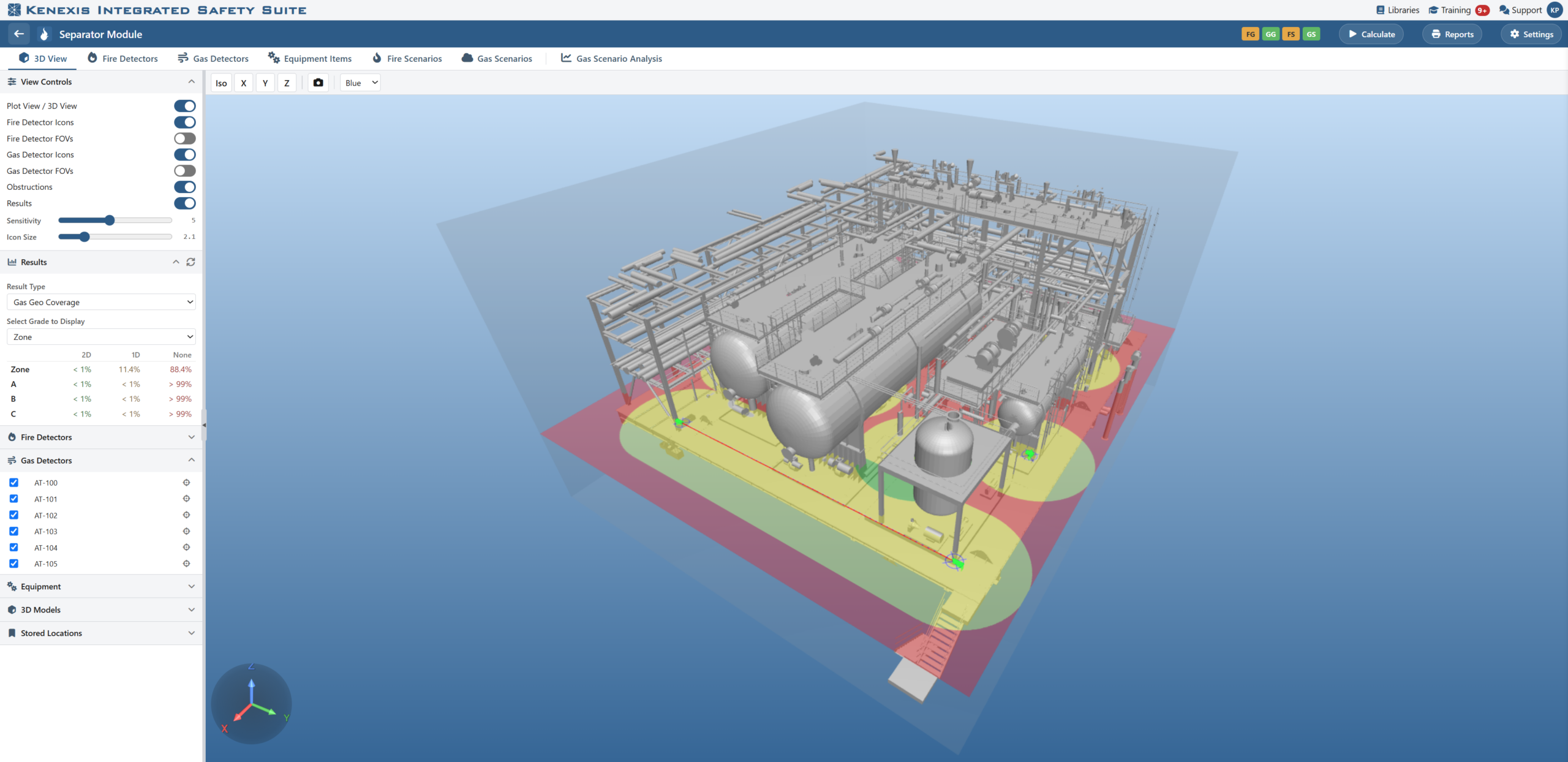
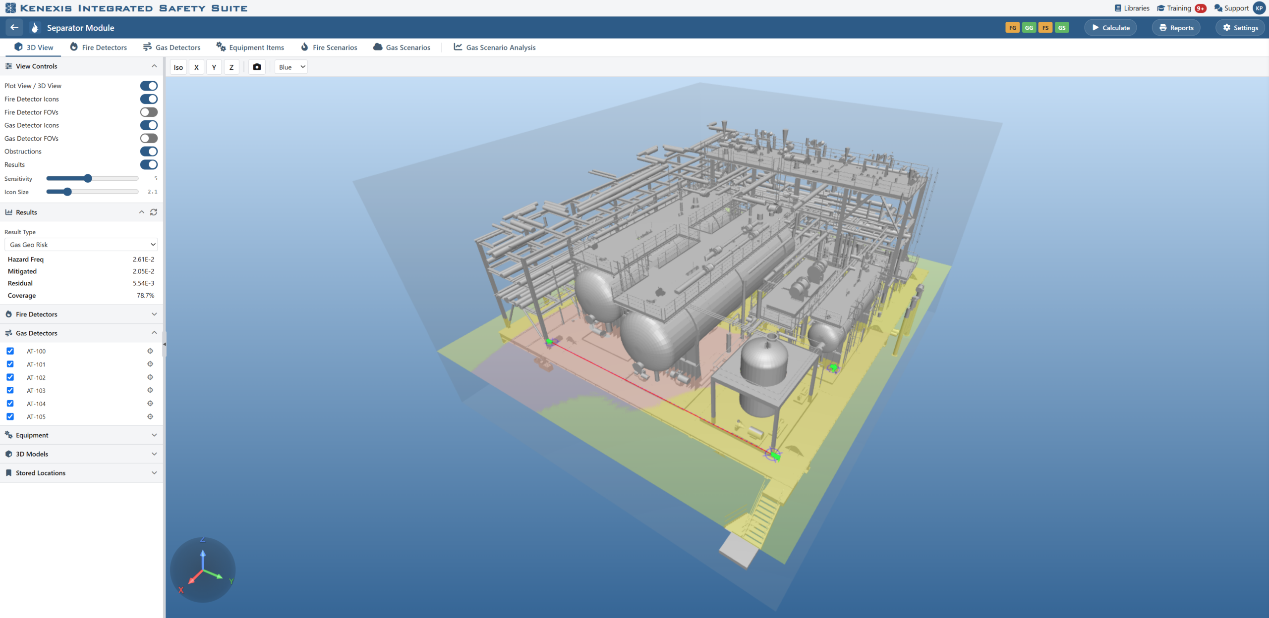
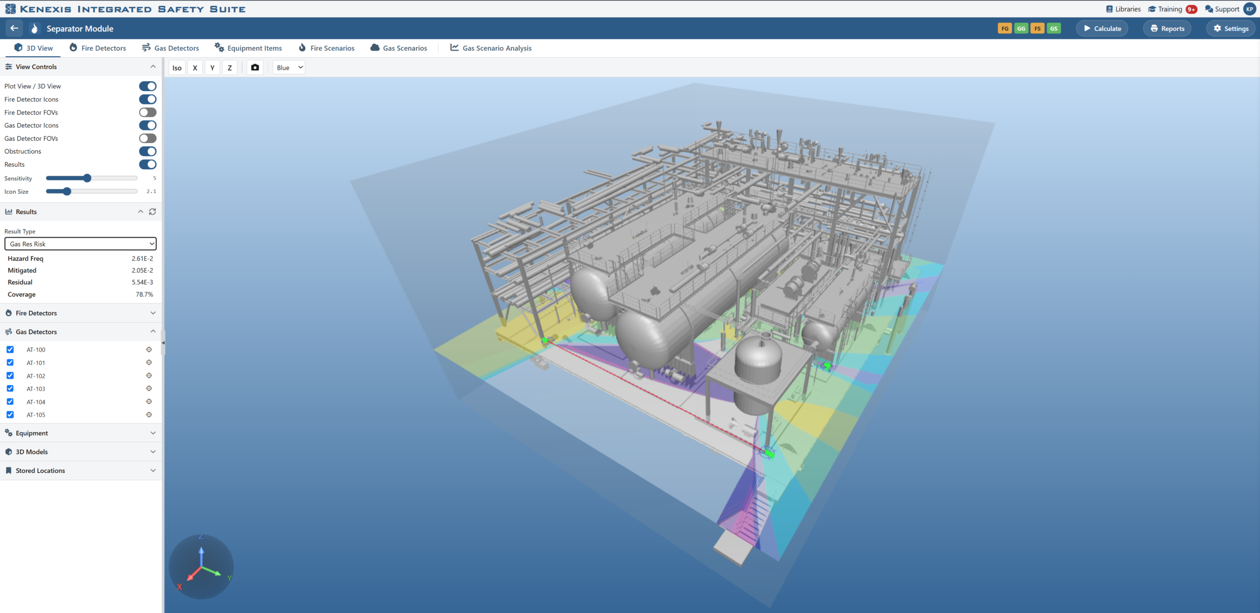
Analyzes detector location and characteristics using both geographic coverage and scenario coverage — and Kenexis® Fire & Gas Mapping is the only major FGM tool that performs both. Geographic coverage measures the fraction of an area or volume where a release would be detectable; scenario coverage measures the fraction of the credible loss-of-containment hazards that the array actually detects — the question an auditor is most likely to ask. The analysis considers the obstructions, consequences, detector equipment, and settings used in the facility under study, producing a geographic risk profile that combines the thousands of consequences possible in a zone, calculates detector coverage by zone, and maps the scenarios detected and not detected.
Gas Geographic Coverage
Gas Geographic Risk
Gas Residual Risk
Fire, Flammable Gas, Toxic Gas, Gas Cloud Imaging & Ultrasonic
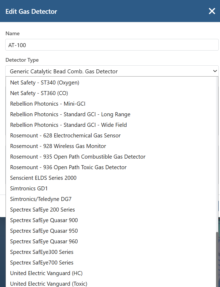
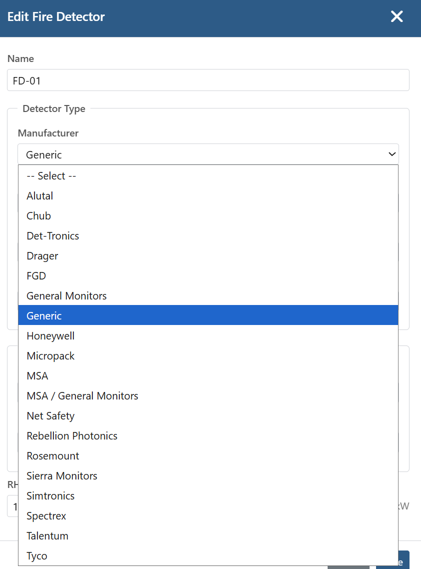
Kenexis® Fire & Gas Mapping supports generic detectors so a design can progress through engineering before specific detectors are chosen, and it models any brand of fire, flammable gas, toxic gas, gas-cloud-imaging, and ultrasonic detector, separately assessing all documented sensitivity settings. The software ships with a database of the most common detection equipment and its performance metrics. Fire detection accurately models cone-of-vision projections as detectors move away from the elevation of interest and rotate away from parallel, using FM3260-certified data.
Gas Detector
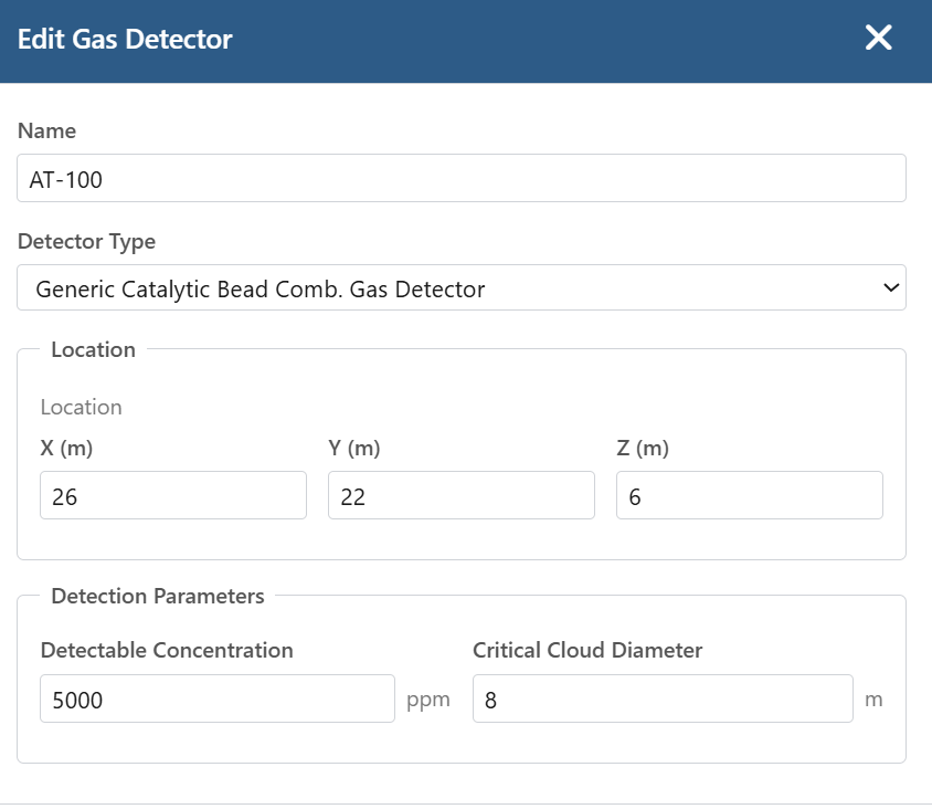
Gas Detector Type
Fire Detector
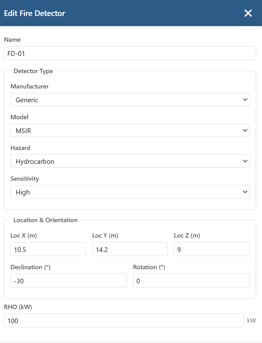
Fire Detector Type
Real Engineering, Not Ray Tracing
Real engineering, not CAD graphics. Most fire and gas mapping tools calculate coverage with ray tracing alone: a fixed geometric cone of vision around each detector, with rays cast outward until they hit equipment or run out — with no calculation of the thermal radiation that actually reaches the detector. Kenexis® Fire & Gas Mapping instead performs a finite-element radiant heat transfer calculation with reverse ray traversal, computing the actual radiant flux at the detector from the fire’s size, material, distance, and obstructions. The result is a physically meaningful detection envelope that adapts to the intensity of the fire — small fires produce small envelopes, large fires produce larger ones — rather than a one-size cone, so the coverage numbers hold up in front of a reviewer who understands fire-detection physics.
Our patented plume model accurately models different fire sizes and materials of interest for each detector as required (for example, methane, hexane, methanol). This substantially increases the accuracy of the detection-capability calculation. (U.S. Patent No. 10,600,057.)
Credentials
ISA-TR84.00.07, Guidance on the Evaluation of Fire, Combustible Gas, and Toxic Gas System Effectiveness, provides guidance on risk- and performance-based FGS design. After years of research, validation, and projects, Kenexis® Fire & Gas Mapping was built to perform sophisticated, accurate coverage calculations based on either geography or consequence modeling — standardizing the path to quantitative coverage targets within your fire and gas design process.
Kenexis holds U.S. Patent No. 10,600,057 for the plume model at the core of this product, authored the ISA Performance-based Fire and Gas Systems Engineering Handbook, teaches the ISA EC56P performance-based fire and gas course, and is active on the ISA TR84.00.07 committee — the very standard the software implements. The fire-detection analysis uses FM3260-certified detector data, and Kenexis maintains a research collaboration with the Purdue Process Safety & Assurance Center (P2SAC).
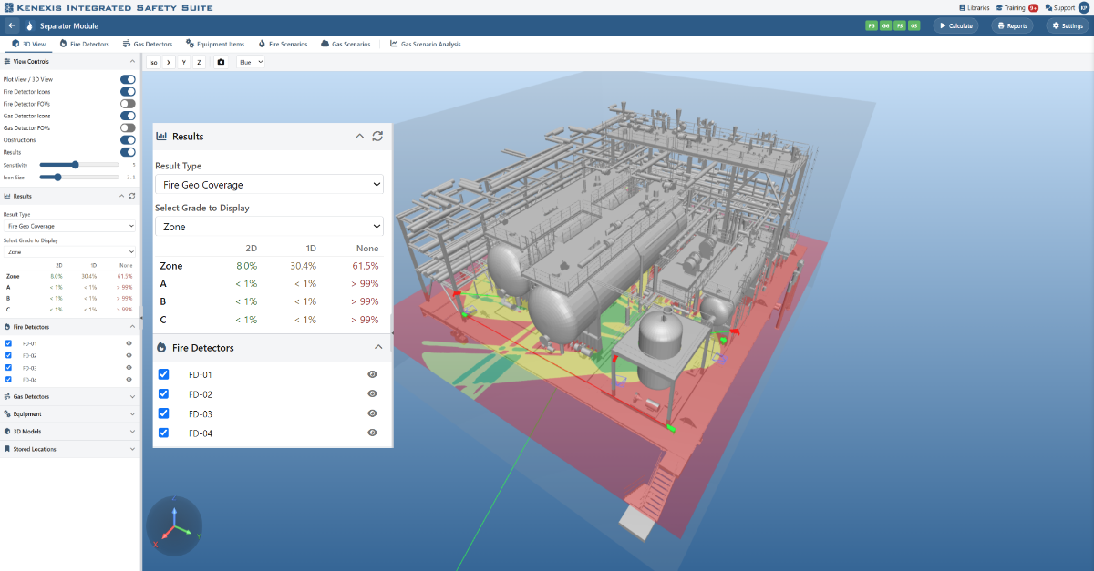
3D CAD Import & 3D Analysis
Supports importing 3D STL files (compatible with most 3D CAD software), lets you build 3D models from basic shapes, and includes 3D analysis features such as the detector’s cone of vision, obstructions, and the orientation of obstruction shadows. If you don’t have a 3D CAD model, you can construct one in Kenexis Fire and Gas Mapping using geometric shapes based on your plot plan. The software analyzes obstruction geometries in all orientations, and results are displayed in color-coded graphical coverage maps and coverage tables.
Optimized Coverage, Fewer Detectors
The payoff is an optimized array — the required coverage achieved with fewer detectors, each one justified. On a recent project Kenexis analyzed an existing 27-detector array and recommended removing 13: coverage in a grade-B area (80% target) moved only from 91% to 86%, while the operator eliminated the lifetime maintenance, proof-test, and calibration cost of 13 detectors that together contributed only about 5% of coverage. Rigorous analysis lets you spend on the detectors that matter and stop spending on the ones that don’t.
Trial Request
Request a free 30-day evaluation of Kenexis® Fire & Gas Mapping. System requirements: none — it runs in your browser on Mac, Linux, or Windows with most browsers.
Pricing
A single concurrent-user license is $13,250 USD/year*.
*Prices shown apply to the United States, Canada and Europe. Prices in other regions may vary.
Please contact Kenexis to request a standard proposal or a 90-day or 180-day project license. If preferred, visit our online store to buy now.
Functional Safety Assessment
New to fire and gas mapping projects? For a reasonable fee, our engineers will perform a Functional Safety Assessment (FGM-FSA) to confirm your project’s scope of work complies with the ISA TR84.00.07 technical report.
For more information: