When performing fire and gas mapping utilizing geographic coverage techniques, one needs to define the extents of the area of concern. This process allows the analyst to define the actual area that must be covered by the fire detectors or the gas detectors. This is only important for geographic coverage methods because geographic methods do not consider the sources of leaks or the size and position of gas clouds resulting from those leaks. When scenario coverage, definition of a graded area is not required as each individual release scenario is individually reviewed. As such, when a coverage target is defined, it needs to be achieved for the entire area in which the process might exist.
The process for defining fire and gas graded areas is very similar to electrical area classification, wherein each potential leak source is defined, and then a certain distance away from that leak source is defined to be part of the graded area. The questions that one needs to consider when making these definitions are: 1) What are the extents of the protected piece of equipment? and, 2) What distance away from the equipment item is required?
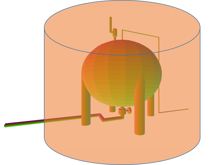
Let’s begin with a definition of the scope of the protected equipment. Consider the LPG storage sphere shown in a 3D view in the Kenexis Effigy software application that is presented below. It is apparent that there is more equipment associated with the vessel than the sphere itself. There pipes, instruments, valves, fittings, flanges, tubing, and other sundry appurtenances of the vessel. All of which are potential leak sources, and which are distributed all around the vessel.

In this figure you can see that while the vessel itself can leak, there are lots of other associated leak sources, including the liquid inlet/outlet valve at the bottom, the liquid piping, the relief valve on top, and the vapor piping on the top. When performing a grading analysis, one needs to determine which of this equipment should be contained in the scope of the graded area. While some would argue that the most likely leak point would be the outlet valve, is the valve is moved on a regular basis, making it subject to high frequency packing leaks, the actual answer is that all of the vessel and its appurtenances need to be adequately covered. The coverage mapping needs to ensure that a leak from the relief valve nozzle flange would be detected in addition to a valve packing leak at the liquid outlet.
The next question to be answer is what area should the coverage include. The answer is the entire area in which a design basis gas cloud or fire could be present. There are two commonly used methods to define the design basis scenario. These are:
- Smallest cloud size that can cause harm
- Smallest cloud size that is possible from a pinhole leak
The first method utilizes publicly available research to determine what is the minimum gas cloud size that is capable of causing a destructive vapor cloud explosion instead of a simple flash fire. The UK HSE has done a lot of research on this topic and concluded that for the moderate obstruction level of a process plant, a methane gas cloud that is less than 5 meters in diameter will not cause a vapor cloud explosion. In more open areas with little or no obstruction, this distance can be increased to 10 meters. More information on this topic can be viewed in another Kenexis blog regarding the origin of the 5 meter grid.
The other approach is to determine the smallest gas cloud that can occur as the result of a release from the piece of equipment. This would be calculated by performing a dispersion modeling analysis of a 1-5 mm hole size which releases material at the process composition, temperature, and pressure.
Once the “inclusion distance”, as determined above is known for the process equipment item under consideration, a volume is created whereby the area outside of the equipment item in “included” in the graded area, up to the calculated inclusion distance. The figure below presents a 2D projection of the graded area onto the plane of a coverage map, and the figure below that is a 3D representation of what is in effect a graded volume.


It is important to remember the the larger graded area will include coverage for leaks from all over the equipment item itself, along with its closely coupled appurtenances. And while this type of graded area analysis is very important for geographic coverage techniques it is not necessary for scenario coverage where the size and location of all of the scenarios is an actual part of the analysis process.