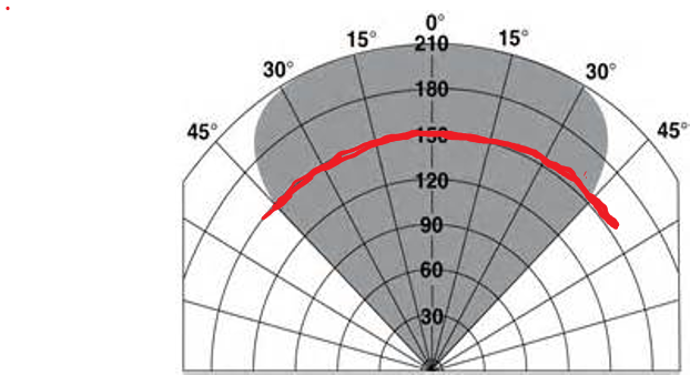
The performance of optical fire detectors is generally defined by the test results that equipment vendors perform utilizing the FM 3260 test specification. FM 3260 testing provides a set of results, that when graphically presented is often referred to as the “cone of vision” of the detector. A typical cone of vision drawing for an optical fire detector is presented below. What is figure presents is the area (shown in grey) where if a design basis fire (1 ft. x 1 ft. n-Heptane pan fire) were to be located, it would be “seen” (i.e., detected) by the fire detector.

The problem with using the FM 3260 results to actually perform fire detector performance modelling is that the performance presented in the FM 3260 results is calculated in ideal laboratory conditions, whereas in a process plant there are conditions present that will act to attenuate, or reduce, the effective distance at which a design basis fire can be seen. Accepted industry practice is to put these attenuating factors into three categories.
- Attenuation due to reduction in sensitivity due to false stimuli (AF1)
- Attenuation due to dirty optics (AF2)
- Attenuation due to off-centerline view (AF3)
These factors work to decrease the effective distance at which a fire can be seen. Each attenuating is defined as the actual distance a fire can be seen divided by the maximum viewing distance as shown in the equipment vendor’s FM3260 report. For instance, if a fire detector is capable of viewing a design basis fire at 100 meters in the FM 3260 test, but during field trials where there are many false stimuli sources the detector can actually only see the fire from 75 meters, then the attenuation factor for false stimuli is 75/100 or AF1= 0.75.
The attenuation factor for false stimuli is a factor that is related to the amount of background infrared radiation that has the effect of “poisoning” a detector’s ability of see an actual fire. This number is generally determined experimentally. Users should consult their equipment vendors for more information regarding quantifying this factor.
The attenuation factor that results from dirty optics is a function of the maximum loss of transmissivity through the lens due to foreign objects (dust, etc.) coating the lens. The loss in transmissivity is generally determined automatically by sophisticated optical fire detectors, and alarms can be set when the transmissivity exceeds set point. This will then trigger a maintenance task to clean the lens and bring the transmissivity back to 100%. A good rule-of-thumb for calculating the dirty-optics attenuation factor is the use the average between the 100% transmissivity of the clean lens and the transmissivity that is associated with a dirty optics alarm. For instance, if a company sets its dirty optics alarms at 70% transmissivity, then the dirty-optics factor should be 100+70/100, or AF2=0.85.
The last attenuation factor is the off-centerline view factor. If you consider the cone-of-vision drawing above, you will note that fires that are directly in front of the fire detector can be seen at 210 feet, but fire that are seen at a 45-degree angle can only be seen at 150 feet. As such, if your FGS mapping technique cannot elegantly account for different detection distance at different angle, you must conservatively use the smallest distance in the cone of vision, as presented in the figure below, this distance would only be 150 ft, resulting in an off-centerline factor of 150/210, or AF3=0.71.

When using Kenexis Effigy™ fire and gas mapping software, incorporating the attenuation factors into a study is a simple matter of selecting the proper detector (including attenuation factors) from the database. Kenexis adjusts the cone-of-vision parameters to include AF1 and AF2. Kenexis Effigy™ does not use AF3, because AF3 is only required if the mapping software or mapping technique cannot elegantly model different viewing distances and different off-centerline angles, as shown in the figure below. Kenexis Effigy™ utilizes a sophisticated NURBS (non-uniform rectilinear b-spline) technique to ensure a high-fidelity presentation of the cone of vision, fully in 3D and at all angles. As such, AF3 is not necessary, and should not be used.
