The mechanism for the bypass needs to meet the requirements of the IEC 61511 (ISA 84) standard. The relevant sections from the 2016 version of IEC 61511 are as follows:
11.7.2.1 Where the SIS operator interface is via the BPCS operator interface, account shall be taken of credible failures that may occur in the BPCS operator interface.
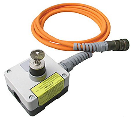
11.7.2.3 Bypass switches or means shall be protected to prevent unauthorized use (e.g., by key locks or passwords in conjunction with effective management controls).
11.7.2.5 The SIS operator interface design (see 11.7.2.7) shall be such as to prevent changes to the SIS application program.
11.7.2.6 Where information is transferred from the BPCS to the SIS, systems, equipment or procedures shall be applied to confirm that the correct information has been transferred and that the safety integrity of the SIS is not compromised.
11.7.2.7 The design of the SIS operator interface via the BPCS operator interface shall be such that provision of incorrect information or data from the BPCS to the SIS shall not compromise safety.
11.7.4.1 The design of any SIS communication interface shall ensure that any failure of the communication interface shall not adversely affect the ability of the SIS to achieve or maintain a safe state of the process.
In order to meet the above requirements for bypass, there are a few general methodologies that are utilized in industry for the normal mode of bypassing, which is bypassing of input devices where a PLC based logic solver is utilized for the SIS. These methodologies can be summarized as follows:
1. Hard-wired bypass switches that are directly wired to inputs to the SIS. This would involve individual keylocked switches for each sensor. This method is costly and cumbersome due to the large number of switches.
2. DCS Interface to SIS communication (soft switch) of bypass status, supplemented by hardware “Bypass Enable” hardwired switch.
3. DCS Interface to SIS communication (soft switch) of bypass status using advanced diagnostics to ensure that the data transfer was appropriate.
4. Use of a separate and dedicated operator interface for the SIS.
As noted in the description, option 1 easily meets all of the requirements listed above, especially energized = bypassed. The problem is that it requires a lot of room to mount all of the required switches (one for each input), the cost is high, and the process for bypass becomes time consuming and tedious, as the bypasser will need to obtain the proper key to put the device into bypass.
Item 2 is quite commonly employed. It starts with a simple “soft” bypass switch configured into the DCS. The ability to achieve the subsequent requirements is based on the additional hardwired switch for “bypass enable”. In this configuration the SIS will only accept a bypass command from the SIS when the soft switch is set to bypass AND the bypass enable key switch is in the bypass position. This arrangement prevents an erroneous message, caused by failure in the DCS, from causing a point to go into bypass. The weakness of this approach is that if the bypass enable switch is not appropriately controlled, it could stay in the enable position for far too much of the time. Also, the achievement of clause 11.7.2.6 and 11.7.2.7 is a matter of opinion with this type of approach, because it can be claimed that the person performing the bypass would be controlling the action, via the bypass enable switch, and then confirming that the appropriate bypass occurred
Item 3 require less hardware, but is more elegant once it is completed. Basically, the SIS and the DCS operator interface need to both be programmed for data integrity checking. The sequence begins with a request for from the DCS to put the SIS point into bypass, the SIS responds with a message back to the DCS requesting confirmation, the DCS interface subsequently responds with a confirmation of the original request. Only after this sequence has been performed is the point allowed to move into bypass. This type of error checking and sequenced communication is effective in meeting the requirements listed above. Many equipment vendors have this type of communication built into their systems, especially if the vendor supplies operator interfaces as well as DCS equipment.
Item 4 seems like it is the most robust, but it is not. Even if a separate operator interface is utilized for bypassing, it will still need to meet the same requirements as shown in Item 2 or Item 3 in order to prevent a single point of failure in the operator interface from resulting in a failure of the SIS because of a failure in the operator interface.

