Originally issued in 2010, ISA has now published the 2nd Edition of TR 84.00.07-2018, Guidelines for Evaluating the Effectiveness of Fire, Combustible Gas, and Toxic Gas Systems. This is a basic summary of these industry norms for Performance-based Fire & Gas System Engineering.
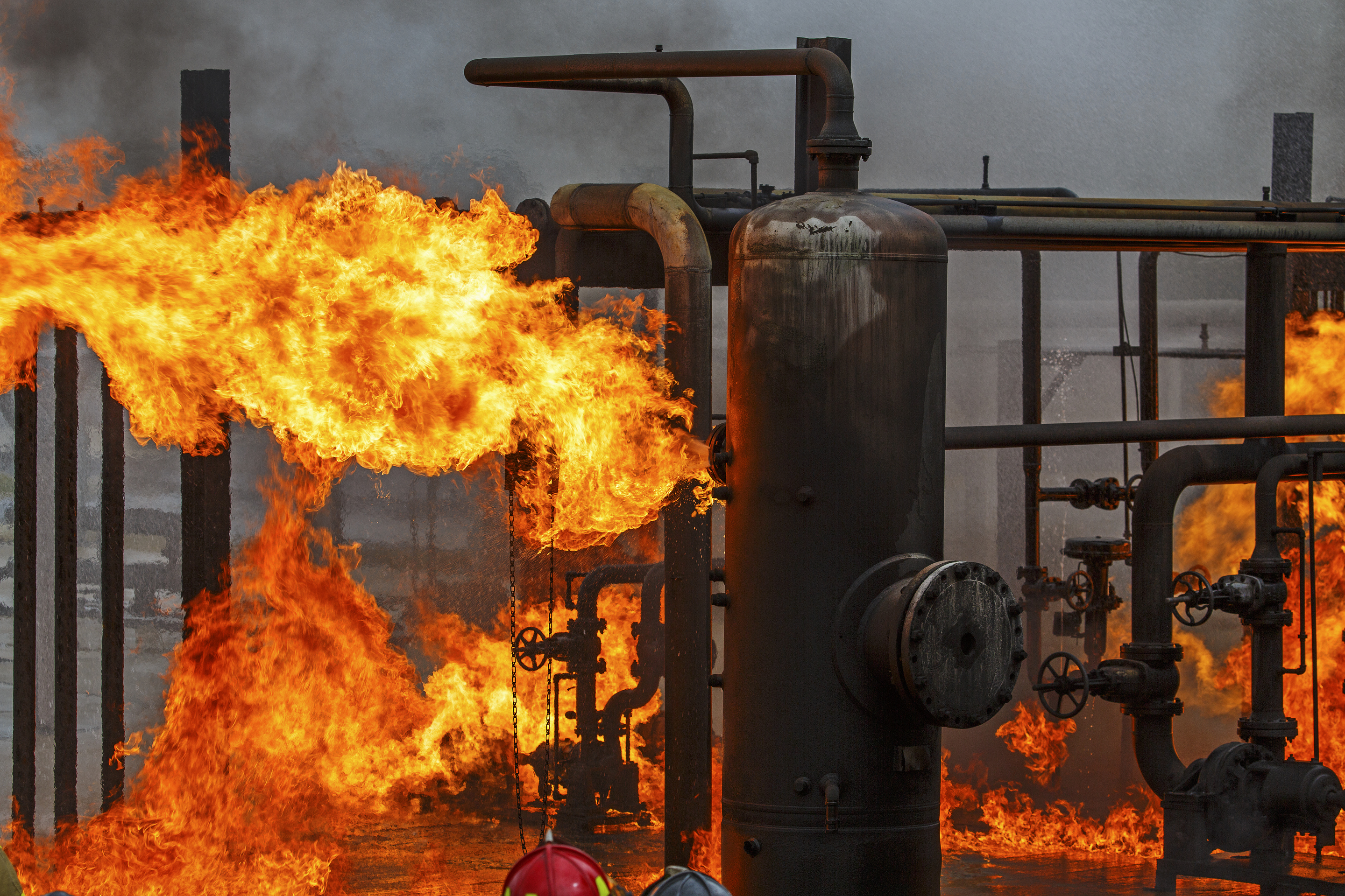
When prevention fails, Fire & Gas Systems have an important role to minimize the hazards and risks in chemical process plants. The Fire & Gas System reduces the likelihood of a small hazard escalating into a catastrophic loss-of-life. In the case of high-hazard applications, Fire & Gas Systems should be designed and implemented based on a good understanding of the hazard and knowledge of the amount of hazard mitigation that is required to achieve overall goals for risk reduction. However, there is a long history of these systems providing inadequate hazard detection of process fires, as well as combustible gas and toxic gas hazards. A study by the UK Health and Safety Executive (HSE) of eight years of data showed that the effective detection rate was only 60%. In the case of high-hazard exposures, prescriptive rules for Fire & Gas System design are usually inadequate, and performance-based fire & gas engineering methods provide for a much-improved design with a higher probability of successful hazard detection and mitigation.
In 2018, The International Society of Automation (ISA) published the second edition of its international norm for performance-based Fire & Gas System engineering. This was developed by a committee of industry experts to provide guidance designing Fire & Gas Systems (FGS) in a way that is consistent with the underlying principles of the international Functional Safety Standard ISA/IEC 61511. These are developed performance-based standards, which are used to specify minimum requirements for designing and managing safety controls. As part of the safety lifecycle, the functional requirements and integrity requirements are established to effectively reduce process-plant risks that are identified by hazard and risk analysis.
Design and implementation of FGS should be done in a way that is consistent with the underlying principles of ISA / IEC 61511. The design and engineering process begins by analyzing the hazard and risk, with the goal of establishing the targets for performance of the Fire & Gas functions. Not all FGS functions should be designed for equal performance, because some hazards / and risks are more severe than others. In the most critical applications, FGS functions can be designed to provide an order-of- magnitude of hazard mitigation and risk reduction. Other applications may not require this high level performance but still provide effective and measurable risk reduction. Still other applications may only require a minimum level of performance that still meets good industry practices.
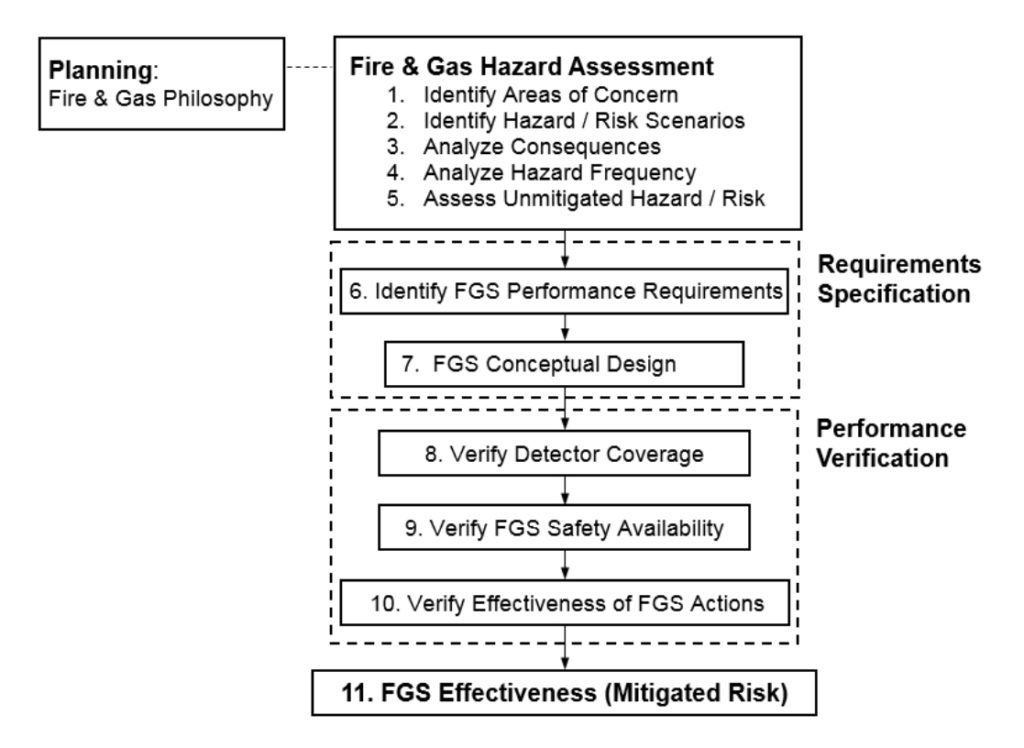
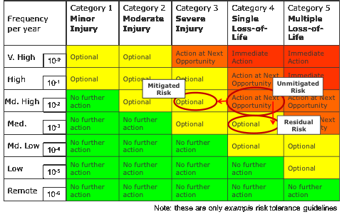
The hazard and risk analysis methods described in international norm ISA TR 84.00.07-2018 can be effectively used to specify a FGS design that achieves the target level of performance, as shown in Figure 1. Engineers then propose a design and verify the design achieves the target level of performance. This performance verification step is accomplished analytically by a multi-step process that includes sophisticated detector coverage mapping. Fire & Gas Mapping ensures that there will be a high probability that the hazards-of-concern will be detected when required. The designers then can have confidence that the FGS will function when it is required to mitigate fire or gas hazards.
ISA TR 84.00.07-2018
The recommended design process requires a Fire & Gas Detection Philosophy to be developed during the planning stage, prior to starting the engineering design. A fire & gas detection philosophy is a well-reasoned technical basis that describes the overall goals for hazard detection and mitigation. It is usually not practical to detect all possible fire hazards or gas hazards in a chemical process. The primary questions to be answered by the philosophy are; the magnitude of hazard should the FGS detection equipment be designed for; and, the type of FGS actions that should be used to successfully mitigate the hazard.
Performance-based fire & gas system design requires an engineering assessment of the specific hazards and risks in the area of concern. With knowledge of the potential for an unmitigated / escalated hazard, the designer can then specify fire & gas functions that will effectively mitigate these hazard / risk scenarios. Although layer of protection analysis (LOPA) is often used to determine Functional Safety requirements, LOPA does have limitations with respect to Fire & Gas hazard mitigation. The ISA TR 84.00.07 provides methods for analyzing the hazard and establishing the performance requirements for hazard mitigation. The hazard analysis determines the performance requirements: which include target detector coverage, as well as requirements for safety availability, and the effectiveness of the FGS mitigation actions.
Fire & Gas Mapping
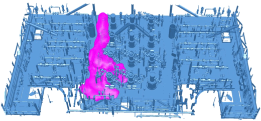
One critical activity during the FGS design is Performance Verification. The detector selection and layout cannot be assumed to be effective; it’s performance should be verified using engineering analysis. Because poor coverage is the biggest problem throughout the history of Fire & Gas Systems, Fire & Gas mapping (Figure 2) was developed by experts to analyze the process-specific factors that determine the number, type, location and configuration of proposed detector design. Mapping verifies the effectiveness of the design toward detecting and mitigating the hazard. An assessment of detector coverage involves analysis of the potential sources of fire and gas within a given monitored process area and the performance of a proposed detector design, including the number, type, location, orientation, and set points of detectors.
Performance Verification
An initial FGS design including a detector layout should be developed during conceptual engineering phase, which is also referred to as front-end engineering design (FEED). The design information that is available at this stage in engineering lifecycle is the major equipment list, process flow diagrams (PFDs), process hazards analysis (PHA) documentation for hazard identification, and the layout of major process equipment. Fire & Gas designers will determine a preliminary layout and detector count that will meet the performance requirements. In the case of an existing facility that is undergoing a redesign or upgrade of the FGS system, the designer makes decisions about the acceptability or reuse of existing equipment. These decisions are made during FEED and documented in the basic engineering package.
Detailed engineering occurs during the Engineering Procurement and Construction (EPC) stage of the engineering lifecycle. Process designers will have developed a mature three-dimensional (3D) process during this stage. The model will have location of piping, utilities, electrical elements, and vendor-supplied packaged equipment. When the 3D model is at the 60% complete milestone, fire & gas detector mapping is completed for performance verification. The detector layout is evaluated by mapping and modified to ensure coverage requirements are achieved. Due to the development of the 3D process model between conceptual engineering and detailed engineering, significant changes to the FGS detector mapping are likely. The detector layout should be re-analyzed by Fire & Gas Mapping and coverage targets should again be verified. At this time, detector placement can optimized using Fire & Gas Mapping. Specifications for FGS maintenance and testing should be developed by considering FGS Safety Availability. Also, issues with constructability and maintainability of detectors are addressed when the 3D detector layout is being developed and verified by Fire & Gas Mapping.
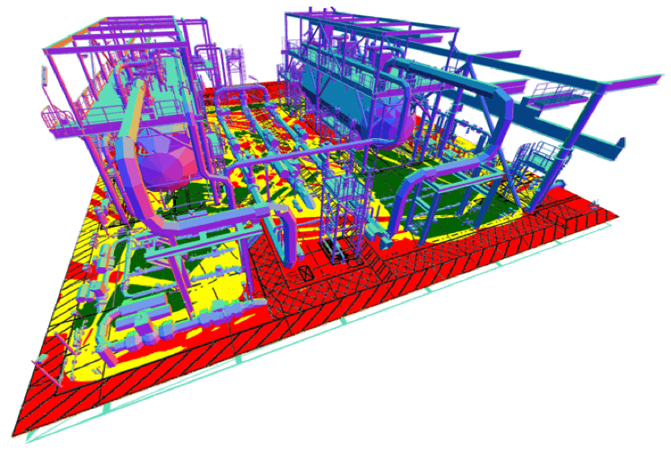
When these standard methods for performance-based Fire & Gas System engineering are used effectively, the operators of chemical process plants can have confidence that hazards will be detected and risk mitigation has been achieved in a way that aligns with risk management objectives (Figure 3).
With best-in-class software products and engineering services, Kenexis has been an industry leader in fire & gas systems for process industries. Kenexis licenses the Effigy™ engineering software for Fire & Gas Mapping, provides recognized training through ISA and online Learning Management System. To learn more about Fire & Gas Mapping and how it integrates into Performance-based fire & gas engineering, contact Kenexis at 614-451-7031 or [email protected].