Companies that are participating in oil and gas production on the Norwegian Continental Shelf know that they are required to meet the NORSOK standards. There is a NORSOK standard that is cutting edge (in comparison to other legislative body guidance in the field of instrumented safeguards), and that standard is NORSOK S-001 Technical Safety. Section 13 of this standard talks about Fire Detection. Specifically, Section 13.4 lays out how the functional requires for a fire detection system shall be determined, and section 13.4.1 specifies the amount of coverage that shall be provided by a fire detection system. The following is required of a fire detection system.
Determination of fire detection coverage (sensor number and distribution) for each area shall be based on flame size, smoke characteristics, and temperature (heat) rise. For a fire (jet and pool) in the hazardous areas, the following apply:
- a flame size of 0.5 meter is diameter and length of 1 meter shall be detected by at least one detector;
- a flame size of 1 meter in diameter and length of 3 meters shall be detected by at least two detectors;
While that requirement may seem simple enough to calculate, most fire and gas mapping software does not consider the actual fire size. With Kenexis Effigy, fire size can be considered two different ways, by using scenario coverage and defining a fire size, or by using geographic coverage, with “plume modeling” selected instead of “point model”. Our patent pending “plume modeling” technology lets you consider the actual dimensions of a fire, accurately accounting for the fact the small diameter obstructions can not block many larger design basis fires, such as the ones listed in NORSOK S-001. For more information on what plume-modeling is and how it works, you can check out an earlier blog from Sean Cunningham.
Click here to see the Plume Fire Model blog
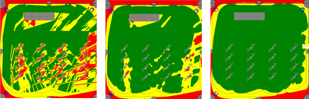
Simpler models for fire detector mapping such as the point model or ray tracing basically consider an infinitely small pathway from the detector out to its cone-of-vision end point (for ray tracing), or from a finite volume that defines a fire location back to the detector (for point modeling). With these models, any obstruction, no matter how small, is expected to be able to obstruct the view of a fire detector and thus create a “shadow” in the coverage map. The reality of the matter is that fires have volume, and something like a 1/8″ diameter instrument tube cannot obstruct a fire whose size is about 1 foot in diameter and 3 feet high (typical for the design basis fire for FM3260 testing of fire detectors, and a common design basis fire size for fire and gas mapping of ‘medium’ grade hazards). When you see a fire coverage map that uses a point model or ray tracing model it will often have very long thin lines that represent shadows cost by small diameter obstructions. In the figure below, which was created in Kenexis Effigy using the “point model” algorithm.

While NORSOK (and reality) requires the fire to have some volume, the point source and ray tracing basically assume that the fire is an infinitely small source of the design basis amount of radiation (usually about 50 kW for medium grade hazard design basis fires). The Kenexis plume model works by taking the total radiation emitted by the fire and spreads it out over the entire surface area of the fire. Then, a fire is considered to be detected if a sufficient amount of the fire’s radiation reaches the detector, considering that some of it will be blocked my obstructions (such as tubing and wiring) but some will not. In order to do this in Effigy, you begin by selecting plume model and setting a fire size in the settings tab, as shown in the figure below.

Looking at the same situation using the NORSOK defined fire sizes of 0.5 meter by 1 meter results in the following coverage map, which is a significant performance improvement over coverage over the point model method. Which makes sense because it’s easier to see a 0.5m x 1m fire than an infinitely small fire…

Changing the fire size from 0.5×1 to 1×3 improves the coverage performance even more.

This figures provide a great insight into the need for defining and modeling different fire sizes in your fire detection coverage mapping. Use of plume model techniques provides the benefit of lower capital costs of fewer detectors through more accurate modeling. This technique is superior when low fidelity 3D models that only include major pieces of equipment. If you don’t use plume modeling techniques for high fidelity 3D models, like the 90% completion models that include instruments, tubing and wiring, the results start to get unrealistic fast, causing large increases the number of detectors ostensibly required to achieve required coverage – which results in unnecessarily high capital expenditures on fire detectors.