
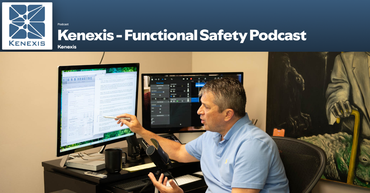
In this episode of the Functional Safety Podcast: Most engineers conflate design with implementation, then wonder why their safety PLC code drifts from intent. In this episode, Ed Marszal draws a hard line between the two phases and walks through Clause 12.4’s exhaustive documentation requirements from originator tracking and SIF-to-module dependency mapping through I/O identification, scan-time limitations, and cybersecurity measures.
Along the way, he vents about redundant SIL labeling, praises the automation potential of large language models for auditor appeasement, and warns against duplicating information that properly belongs in a single corporate coding standard. The episode covers the full lettered list of Clause 12.4.2, ending with a preview of library functions and program structure in the next installment. Anyone actually writing or reviewing safety PLC code will find the hour well spent.
Grab your headphones and let’s streamline your workflow!
Tune in to the latest episode of the Kenexis Functional Safety Podcast, hosted by Ed Marszal, President and CEO of Kenexis. Now available on Spotify and Apple Podcasts, Ed offers his expert insights on the IEC 61511 standard.
With decades of experience in safety instrumented systems and as a Principal Engineer, Ed has a unique perspective to offer. He has been an active contributor to the ISA 84 committee since 1994, adding to his deep understanding of the field.
In this inaugural season, Ed delves into the IEC 61511 standard, unpacking the meaning behind each word and providing a thorough interpretation of its application. Through personal stories from his career and committee work, he offers valuable context and insights for professionals in the industry.
Full episode transcript
Introduction and Episode Overview
At the risk of preventing you from doing some unnecessary work, let me tell you, a lot of people do application program design and implementation at the same time.
Welcome to the Kenexis Functional Safety Podcast. I’m your host, Ed Marszal, President and CEO of Kenexis. Kenexis is a technical safety consultancy that helps chemical process industry companies to analyze risk and design engineered safeguards like safety instrumented systems and fire and gas detection systems. Kenexis also provides the industry-leading suite of software tools, including our best-in-class Vertigo software for SIS safety lifecycle management.
In this first season of the podcast, we are going to focus on the IEC 61511 standard, doing a deep dive into the standard, including more depth of information on what the standard means and how to apply it, brought to life with personal war stories and behind-the-scenes discussions of the committee members as we develop the standard in ISA 84 and IEC SC 65.
Before we start, a little disclaimer: I will be providing my opinion on technical and engineering topics. This information is provided on a best effort basis and is of a general nature. The information presented in this podcast might not be applicable to your specific application. It is the obligation of every engineer to thoroughly analyze any system that they are designing and not blindly rely on any general advice presented in this podcast.
Recap: Design to Implementation Transition
All right, now that we’ve gotten through the application program design, we can get into the application program implementation.
So 12.3 was application program design. It took us a couple did it take us three weeks or two weeks, two to three weeks to get through application program design. Now we were in application program implementation and theoretically we should have written a bunch of documentation, paper, databases, free form charts, whatever it is you’re using to do your documentation these days, not necessarily pen and paper. I know that pen and paper for me are kind of a relic of the past, but after we do our design, now we’re in the implementation phase where we make that design tangible by making it code.
So the executable code that’s going to be running in the safety PLC is what we are generating right now. Typically, that means we’re going to be doing a lot of work in the maintenance and engineering interface tool that we use to generate that application code, which then gets turned into executable or object code and then uploaded into the actual processor itself. So in theory, we put together a big long plan about how we’re going to write code and then we’re going to write the code.
Now, in a lot of cases, we’re going to go pretty direct where the most common approach is: I’m going to just start writing code directly off of my cause and effect diagram and some notes. And as we travel into the future, you know, more and more of this is going to get automated. I mean, if you think that AI coding is going to be limited to people creating web pages, let me assure you that it is not. So, something to think about as we’re going down this road.
Clause 12.4.1 and 12.4.2 Overview
Okay, so clause 12.4 is application program implementation. Clause 12.4.1 is kind of the starting point for this clause, and it says the application program development methodology shall comply with two things, it shall comply with two things with the development tools and the restrictions given by the manufacturer of the SI SPE subsystem on which the application program shall be used.
Okay, so let’s unpack this first requirement. All of clause 12.4.1 was simply that one sentence where basically the standard is telling you that you are using a tool to develop your application program. That tool is being provided to you by the manufacturer of the safety instrumented system programmable electronic subsystem. So it’s always going to be a PE, it’s always going to be programmable electronic because, well, if it’s not programmable, then there is no application program. So, generally, you’re going to be working on through the development tools provided by that manufacturer.
What does that mean? Those development tools are going to be the maintenance and engineering interface. We already discussed the maintenance and engineering interface back in clause 12. This is the application program that allows you to write. It’s your code development environment. Or an IDE, as the coders would say, integrated development environment for actually writing, testing, debugging your code, making copies, making revisions, uploading, downloading, etc. That’s the tool, that’s a development tool.
Now, the clause says that your method, whatever you do to write the program, has to be consistent with the tool that you’re using, which does that need to be said? Is that obvious on its face? Obviously, if you need a tool to write code, then whatever method you use to write the code has to be consistent with that tool. Okay, now what’s a little bit more interesting is the second part of that, which is the tool and the restrictions. So there may be restrictions on how you write code, what code tech what coding techniques you’re allowed to use, what approaches you’re allowed to use.
So those restrictions are all going to be listed in the manufacturer’s documentation.
Specifically, there shall be, there will be, there shall be a safety manual associated with your PE logic solver that will give you the limitations on what you need to do in the application program development. And that’s bigger than just actually typing in the code. That’s testing the code, debugging the code, uploading the code, downloading the code, making revisions, storing revisions, and so on.
So, as you’re developing your software, step one, absolutely, step one, needed to be reading through the documentation provided by the equipment vendor on how to program their device, specifically looking at the safety manual and looking at the restrictions on how you do your coding.
Now another thing in this clause that’s a little bit interesting is that it says that the methodology shall comply with the development tools and restrictions given by the manufacturer. Now, in some cases, you might be able to download code directly to the logic solver without using the manufacturer’s development tools.
There are some software tools out there that will still allow you to, I’m sorry, some PE logic solvers that will allow third-party engineering tools to be used to write the code, and those third-party tools will dump your object code or your executable code directly into your safety PLC.
So if that is the case, you’re still going to need to follow the restrictions from your hardware vendor, but you know, more and more, that is extremely rare, extremely odd that you would not use the development tool provided by the hardware vendor.
Back in the day, these software tools, the maintenance and engineering interfaces, the software vendors used to charge a lot of money for these tools, and the tools honestly were not that sophisticated.
So third parties popped up to fill in that economic gap that says, well, you can write your code here for a much lower price than buying the maintenance and engineering interface directly from your equipment vendor, but more and more the equipment vendors C clamp down on that activity, make their maintenance and engineering interface a little bit more financially attractive to use than trying to work with some third-party vendor. Okay, now we are going to get into clause 12.4.2. And the question is: Will we be able to get all the way through clause 12.4.2 in this session?
So when I started this session, I was assuming I was going to be able to bang out all the way through clause 12.4, but that might not actually happen seeing how we’re already 10 minutes into the episode, and I’ve just gotten one sentence of the clause written, so we’ll probably do a wrap at the end of 124-2 if we can get even get there.
Why? Ed, why does one clause take so long? Well, it’s because it’s one clause in L part. So, how many is L? Well, it’s a lot. It’s more than 10.
So, let’s go ahead and go through each one of the sub-sub-sub-clauses or the lettered list of items under clause 12.4.2.
So the stem for clause 12.4.2 is: the following information shall be contained in the application program or related documentation. So, what actually needs to exist in the application program, there are L items, and it’s more than just what needs to be included in the application program. There is related documentation to the application program.
So, some of these bits of information you can store externally to the program, and maybe it’s more of a code file or a source code file in the maintenance and engineering interface, and not all of that source code is going to make it down into the executable that’s going to get loaded into the safety PLC.
Okay, number one is a great example of what might not make it into the actual executable code, but could be stored in the object code or the source code, or might not even be listed in the maintenance and engineering interface at all, and might be stored externally.
Items A-C: Originator, Purpose, Safety Manual Versions
So letter A is the first item and it says that the application program or related documentation shall include the application program originator. Who is the programmer? Who is the author? Who wrote the program? Who wrote the first version of the program? That’s why we say originator instead of programmer because they’re over time is probably going to be many, many, many programmers.
So we want to know who wrote Rev A, that first original revision of the software. Very rare for that to make it all the way down to the safety PLC. Very common for that to be included in the maintenance and engineering interface. But if it’s not, then there’s still going to be some sort of documentation that you can generate to associate with each revision of the file with who the author is.
Letter B of clause 1242 states the application program or related documentation shall include a description of the purpose of the application program.
So once again, we have kind of header information that the program doesn’t do anything with in runtime, doesn’t need to know in runtime. It’s just kind of administrative information that sits on top. So, once again, that description might sit in the source code in the maintenance and engineering interface, or it might be an entirely separate document for revision tracking, what have you.
Item C: The application program or related documentation or related documentation shall include the versions of the safety manuals that were used.
This goes back to clause 1241. We need to make sure that the programmers read through the safety manual to understand what the restrictions are on how it’s going to be used. So, excuse me, so we need to list out what versions of the safety manual were used, and generally, you’re also going to need to have that information on a revision-by-revision basis. So, while you’re doing your revision tracking, you would want to know that. So that revision tracking, sometimes it sits in the source code, sometimes it sits in a separate document in the maintenance and engineering interface.
Other times, if you’re using some relatively unsophisticated software, you might have to track that separately yourself.
Item D: SIF Dependency on Program Modules
All right, application or item number D. So item D states: the application program or related documentation shall contain D, identification of the dependency of each SIF on the parts in parentheses modules of the application program.
Okay, this is something that is kind of over the top back in the 90s and 2000s when I was first writing my first application programs and safety PLCs.
That, excuse me, sorry about that. Let me get my production water going.
Um, that is something that I would never do. So it’s kind of inherently going to be tracked in the program itself, especially if you’re using things like function block diagrams or you’re defining things and it’s honestly in in most limited variability languages. It’s kind of traceable just looking at the application code.
So when I have a sheet of a function block diagram that is dedicated to a safety instrumented function. When I look at that safety instrumented function’s code, I will see function block diagrams like a two out of three voter on input data coming in. Well, that two out of three voter is a module, a subroutine, however, you want to refer to it, and it’s very clear that I’m calling that subroutine when I’m looking at it. So, in the more visual limited variability languages, it’s hard not to have that inherently documented just in the code itself.
But if you’re writing a safety instrumented function in something like a structured text, which I don’t know why you would ever want to do that. But if you use structured text to define a safety instrumented function, that structured text might be calling other subroutines to execute things, just like I said, like a two out of three voter. And you would see those subroutine calls in the structured text. So I don’t know how
I feel about having something like a separate document that says this SIF uses these function blocks, this SIF uses these function blocks. I don’t see a whole lot of value in it. I don’t see a whole lot of need for it. I have never done it, but well, the standard says what it says. You can read the text directly out of the standard and use your own judgment on the level of detail that you need to create.
But I also know that I could probably feed my ladder logic or my function block diagrams into a large language model and have it generate on a SIF by SIF basis what all of the subroutines that it’s calling, the modules that it’s calling are. So if you need to recreate it for some pesky auditor, well, if it were me, I would just hand that over to Claude, let him chew on it for you know 30, 40 seconds and generate a document.
Items E-F: Traceability and SIF/SIL Identification
Okay, the next item up is going to be 12.4.2e. And here we state the application program or related documentation shall contain E traceability to the application program safety requirements specification.
So, where did the requirements that are being executed in the application program come from? How do you document that? Usually, notes, references that are contained in the application program source code itself. I’m sorry, not the source code itself, because you don’t need to know that to execute the program. So that kind of sits in the well, the source code, but not the compiled object code.
And of course, if um your application program, your maintenance and engineering interface doesn’t allow document you to that type of thing as notes or comments, then you’re going to need to document it elsewhere.
Okay, item F: so the application program or related documentation shall contain an identification of each SIF and its SIL.
Boo. Boo. Man, why are we repeating unnecessary information all over the place? Come on, people. This is ridiculous. Why does the application program need to know what the SIL is. I don’t, I specifically don’t want you to put the SIL target into the application code. That’s nuts. Not even as a comment. Well, maybe as a comment, but now you’re duplicating information in multiple places for no good reason. If you know what the SIF is, defining what the SIF is when you’re in your application logic in terms of this safety instrumented function, this tag, that’s fine.
But you can always cross-reference where those SIL targets were, what those SIL targets are by pointing back to other information so you don’t need to make multiple copies of this stuff. Boo! All right, well, identification of each SIF. I will take that. I will take that in terms of knowing which SIF is executing where in your function block diagrams and in your ladder logic. It’s not uncommon to have a separate page of function block diagram logic for every safety instrumented function. Not uncommon at all. You know, and you could kind of use a similar approach in ladder logic also.
Even if you have just one set of ladder logic for your whole safety PLC, you are kind of breaking things down by rungs, and you could put some commentary in there.
Items G-I: Symbols, I/O, and Communications
Alright, next item is item G. So application program or related documentation shall contain G, identification and description of the symbols used, including logic conventions, standard library functions, application library functions. Why?
Why are they making me generate so, so, so many pages of unnecessary documentation that’s going to fall into disrepair because of disuse, because it’s just generally not necessary.
Now, things like descriptions of symbols used, logic conventions, standard library functions, application library functions.
I don’t want you ever, ever to try to put that in your code because that’s something that you write it once and forget it. This, remember two, three episodes ago, I said that your site or your organization should have a standard on how you write code in your PLCs, including things like description symbols, logic conventions, standard library functions, naming conventions. All of that should be in one document. You can feel free to refer to it in the notes of your application code. Yes, this program was written based on this standard.
I don’t want you recreating and rewriting all that information for every program. It’s a waste of time, but even worse, you’re going to end up with old, inconsistent information in your programs, it’s unacceptable. Unacceptable. All right, moving along.
So for clause 10.4 point two uh we are now on letter H in the list so uh letter H in the list is going to be application program or related documentation shall include identification of the SIS logic solver input and output signals.
So somewhere in your application program, you’re going to have more of what I would refer to as a configuration step as opposed to a programming step.
You need to list out what all your I/O. Points are, what rack slot and channel they’re landing in, whether that rack slot and channel is an analog input, digital input, analog output, whatever it is, electrical information, range information, all of that is part of the configuration, and it is something that is going to get downloaded into your PLC for sure, but it’s also something that when you print out your application program, that application information should also be uh printable or something that uh the engineering team can get a hard copy of and review.
Well, I guess technically they don’t need to get a hard copy of it. An electronic copy would be fine.
Okay, next item up on the list is going to be item I. So the application program or related information shall contain I where the overall SIS utilizes utilizes, uses, utilizes communications, a description of the communications information flow.
Now, this item I has an informative note associated with it, which says that you need to provide or an example would be where a SIF uses several logic solvers. Okay, that’s some complicated information.
Where a SIF uses several logic solvers, how they’re wired together is something that should have been in the safety requirement specification. To the degree where it is required, your maintenance and engineering interface is going to allow you to configure all of the cards, including the communications cards. And outputting information and inputting information to and from communication cards is something that you’re going to set up in the configuration settings of the device.
So, all that should be stuff that you have to input into the safety PLC and kind of a higher-level discussion of what gets communicated, how it gets communicated is something that is going to sit in the overall safety requirement specification. It might sit in a separate application program requirement specification if you decide to write one, but I think I have thoroughly discouraged you from writing a separate document by this point in time. At least I am hoping that’s what I have done.
Item J: Program Structure and Scan Times
Okay, next item up is going to be J. So the application program or related documentation shall include J. A description of the program structure, including a description of the order of the logical processing of data with respect to the input-output subsystems and any limitations imposed by scan times. Hmm.
Well, a lot of this we have already talked about in the design portion. We talked about it way back in the hardware SRS specification section.
So when you are running a safety PLC, as I mentioned in a previous episode, the protocol is generally write to the outputs, read the inputs, execute the code, and wait for the next scan. Now it is super important that all of that can happen comfortably inside the scan time because if you exceed your scan time with that work, then most safety PLCs are not going to crash, they’re simply going to start the next scan late. And that can result in all kinds of conundrums and confusion and bad control and alarms going off, and just stuff that we don’t want to have happen.
So, in our safety requirement specifications, those limitations imposed by scan times should have already been documented there. We know how quickly we want the scan to go or how quickly we need the scan to go. And when we write our program as we’re doing it we need to be looking at that execution time in comparison to the scan time that you’ve set based on the safety requirement specifications or set with a limitation understood coming from the safety requirement specifications.
The order of processing that comes in two parts. The typical write, read, execute is something that generally speaking you don’t have any control of. The equipment vendor has decided how that order of operations is going to happen, and it happens. There’s nothing you can do to change it, modify it, etc. For the most part, you know, I haven’t seen everything, so maybe somebody allows you to change the order of operations. The other thing to think about is which order the ladder logic rungs fire in.
I mean, there’s an expectation from anyone who’s been writing ladder logic that it will sequentially fire numerically. Rung one is going to complete before rung two starts, etc., etc., etc., etc. Just a nice systematic flow that we got used to back in the days of QBasic in the 70s and 80s.
All right, the function block diagrams, on the other hand, now we’ve got kind of more of a more visual tool, and you’re going to need to understand that if you have a whole bunch of function block diagrams, which one is going to fire first, which one is going to fire last? You’re going to want to make sure that that’s happening systematically and that you can control which one fires first, which one fires last, and making sure one page is done before the next page starts. So, all of that is going to be configurable in your maintenance and engineering interface.
If you don’t know the order in which things execute, shame on you. Go look at your safety PLC’s safety manual. Go out on the cloud. Ask Claude. Ask Gemini. Ask Grok how it works so that you know in the future how it works and don’t mess things up. So, like a description of that stuff, do I feel it’s necessary for you to put it in your application program as an inf a comment? No, I really don’t. Because this information should all be spelled out in your SRS document that you did in clause 10 and in your safety manual. So repeating it here, I don’t like the idea of repeating it here.
Instead, I would at most refer back to those documents where this information actually lives okay.
Item K: Data Integrity and Cybersecurity Measures
Uh, item K on my list. So, the application program or related documentation shall contain item K, which is, if required by the SRS, the means by which three things happen. So our lettered list, item K, has a bulleted list of three items.
So, if required by the SRS, we need to document the correctness or the mechanism by which the correctness of field data is ensured Insured.
So, if you need to do a diagnostic that compares a BPCS signal to the SIS signal, you need to code that up, okay. If you need to do a comparison of the three transmitters in the two out of three vote coming into your PLC, you need to code that up. Okay, good. That should have been documented in your SRS, and your code should have done that. And honestly, for something like a two out of three vote, that should really be baked in to your function block, your library subroutine or function block that handles these things.
Second bullet point states you need to program the way the correctness of data sent over a COM link is ensured.
For example, when communicating from an HMI before implementation of a command and ACK ACK meaning acknowledge ACK or acknowledge is transmitted. So if it is important for your safety PLC, for the basic process control system to communicate which batch step you were in, you need to write the program for how you ensure that that data is correct, which might include communicating back to the basic process control system that you’ve received a piece of information. And getting the basic process control system to acknowledge that that piece of information is correct.
Those of you that have taken training classes with me, or possibly somewhere earlier on in the podcast, I use the term digital ping-pong. That’s what we’re talking about here. So it’s not just that. So there are things like plausibility checks, range checks, all of that. If you need it, if you specced it in the SRS, well, you’re going to need to write the code here to make sure that it happens. And the last bullet point of item K is that you’re going to need to code up the mechanism by which communications are made secure.
The cyber security measures. So if you are implementing cyber security measures inside the safety PLC, you’re going to need to code them up. But most of the cybersecurity is going to be external. So your safety PLC is in a zone. And consumers of safety PLC data that are in the zone are generally considered to be safe. Where things get sticky is data that you’re trying to send out of the zone and data that’s coming into the zone.
So if you wanted to send a bypass signal from a remote operator station, that might need to go through a conduit as the 62443 standard calls it, which is something like a gateway or a firewall that’s going to check and make sure that that signal is coming from a valid address on a valid port, going to a valid location on a valid port before that information is let through.
Now, all that definition of what’s going on in those firewalls or the structure and programming of the conduits, I would generally say that that’s outside the scope of what you’re doing in the application program for your safety PLC. Right now, put on the spot, I can’t think of anything that would be inside your application program that is cyber security-specific programming. But hey, send me an email if you disagree. I would like to know. But if there is something, you need to make sure that it gets coded up.
Item L: Version Identification and Change History
All right, the last item for 12.42, and actually, honestly, the last item for this session also is going to be that the application program or related documentation needs to include L, a version identification and a history of changes. Okay, version identification.
This is a slam dunk. If your maintenance and engineering interface software don’t handle what revision number you’re pushing back and forth automatically, you should probably get your software and your safety PLC from somebody else. This is table stakes at this point in time.
And also, that entire revision log or the history of changes should be securely stored with backups, all that other good stuff at the maintenance and engineering interface.
Now, if you’re using some Garbo software, you might need to track that history of changes yourself. So use something maybe like a GitHub equivalent where you’re going to store the source code of each revision, along with kind of a database of when, why, who made the change, who approved the change, and so on. those revision tabs that you’re used to looking at, you’re going to use that same kind of information to maintain a revision history of the program in your safety PLC. But goodness gracious, I hope that your equipment vendor has already taken care of all of this for you.
Episode Wrap-Up and Next Episode Preview
Okay, with that, not the longest session of the podcast we’ve ever done, but I’m going to go ahead and make a wrap right here because we still have a lot to go in clause 12.4, and I don’t want to give it short shrift. So we will pick up clause 12.4.3 and 12.4.4 in the next episode of the podcast.
So, 12.4.3 is going to talk about application program library functions, how you use library functions, who created those library functions, are they coming from the equipment vendor? Are you allowed to use them? Can you make your own? There’s a bit to discuss there with regards to library functions or library subroutines. That all is coming to a head right now in the larger software development world because a lot of software applications out there are using open source libraries.
Now, I am not familiar at this point in time with any open source libraries of SIS functions, but then again, maybe there are, maybe they are out there. Just maintaining the provenance of what’s been done by an open source group, trusting that to prevent you from getting killed. That’s a bit of a stretch. Anyway, we’ll talk about that.
Also, clause 12.4.4 is going to talk about the structure of the application program: testability, traceability, decomposition, functionality, subroutines, global variables, all that stuff. So 12.4.3 and 4.4 are the things that we are going to talk about next week.
That is all that I have for you today. I will talk to you again next week.
Vertigo Product Overview
Now that you’ve heard some insights on technical safety, functional safety, and the IEC 61511 standard, let me tell you a little bit more about how to easily and effectively implement the safety lifecycle using the Kenexis integrated safety suite and our SIS safety lifecycle management tool, Vertigo. Vertigo is a comprehensive tool set for performing assessment calculations, documenting, and maintaining the design of safety instrumented systems.
Analysis begins with importing or synchronizing a list of safety instrumented functions with their definitions and associated performance targets from our open PHA tool for HAZOP and LOPA documentation.
Each safety function can then be analyzed by performing a SIL verification calculation, complete with a collection of tools for optimizing designs and a database of thousands of potential instruments to define failure rates and diagnostic coverage capabilities. After the SIL verification calculations are defined, you can build an SRS by automatically generating a cause and effect diagram from the SIF definitions and other defined instruments.
Each SIS instrument will include a customizable data sheet and general requirements that are applicable to the SIS as a whole and can be entered individually or even bulk imported from customizable libraries.
After the design phase, you can even use Vertigo to track and document testing throughout the entire life of the facility. Kenexis Vertigo is the most integrated easy-to-use enterprise tool for allowing the development of SIS design basis information more efficiently and effectively than any other software application.